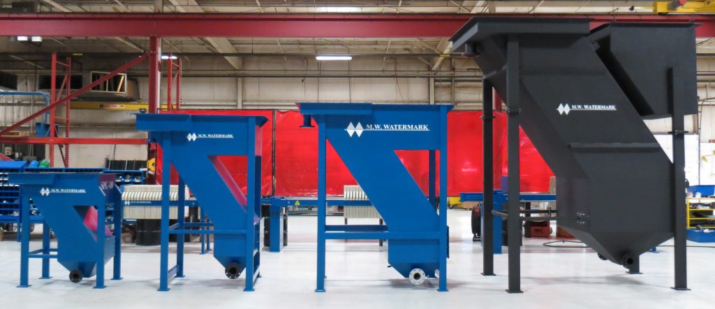
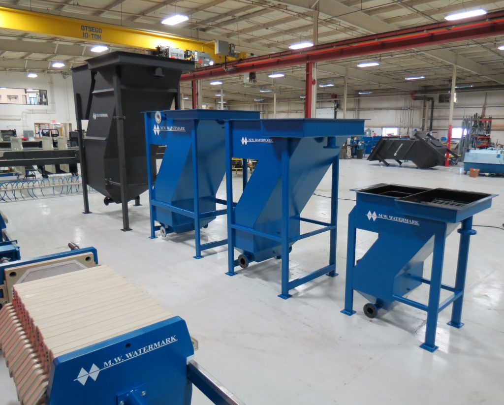
Wastewater Clarifiers – Slant Plate (SPC) and Low Profile (LPC)
When it’s necessary to remove particles from a large volume of water, often the best option is to go with a wastewater clarifier. M.W. Watermark™ offers high quality, American-made slant plate and low profile clarifiers that are designed to achieve the ultimate goal of keeping the planet’s water supply safe for generations to come.
SPC
LPC
The M.W. Watermark Slant Plate Clarifier (SPC)
Our slant plate wastewater clarifier is one of the most efficient methods available for the removal of solids from process liquid and waste. While there exists a variety of designs for such devices, utilizing inclined plates allows us to pack the widest possible combined plate area into a compact floor space. Plates are placed close together, and settling surfaces are stacked to form a settling area 10 times larger than the total area occupied by the machine.
Click Here to Download Our Slant Plate Clarifier Brochure
Learn More on Our Blog…
“Slant Plate vs. Low Profile Clarifier” – Read more.
“What is a Slant Plate Clarifier?” – Read more.
“Slant Plate or Dissolved Air Flotation (DAF) Clarifier?” – Read more.
“Coating Types for Your Industrial Filtration Equipment” – Read more.
Need feed pumps, tanks or an electrical control cabinet? M.W. Watermark can supply everything you need for a complete wastewater treatment system.
Does your spec call for a Dissolved Air Flotation (DAF) Clarifier? Visit our DAF webpage to learn more.
Slant Plate Clarifier Product Features
Within our range of slant plate clarifiers, we offer nine standard-sized models, handling between 5 and 400 GPM, a sludge holding capacity between 17 and 960 gallons, and a plate area of between 16 and 1,680 square feet. That large capacity comes at very little cost in terms of floor space; sizes range from 45″ x 23″ to 170″ x 120″, with heights ranging from 51″ to 147″. The machines feature no moving parts, constructed using 1/4″ steel and dye-pen tested welding. Integral flash mixing and flocculation tanks help to increase efficiency, and the entire structure is sandblasted, primed, and painted to provide maximum chemical resistance. Each device comes equipped with 1/4″ thick removable PVC settling plates, dual sludge outlet flanges, sludge sampling ports, and a large side-access hatch to allow for easy maintenance.
Available Options
In addition to the standard features, our slant plate clarifiers can also be equipped with:
- Mixers for flash and flocculation tanks.
- Coal-tar epoxy interior coating (other coatings and materials are available).
- Influent feed and sludge discharge pumps.
- Custom designs available.
- PolyMark™ polymer delivery systems.
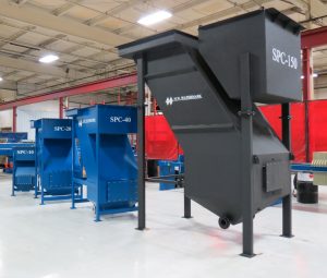
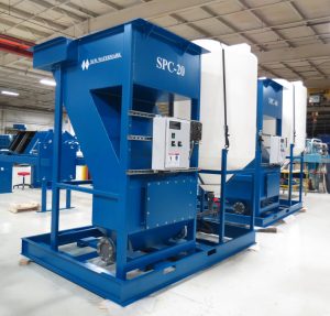
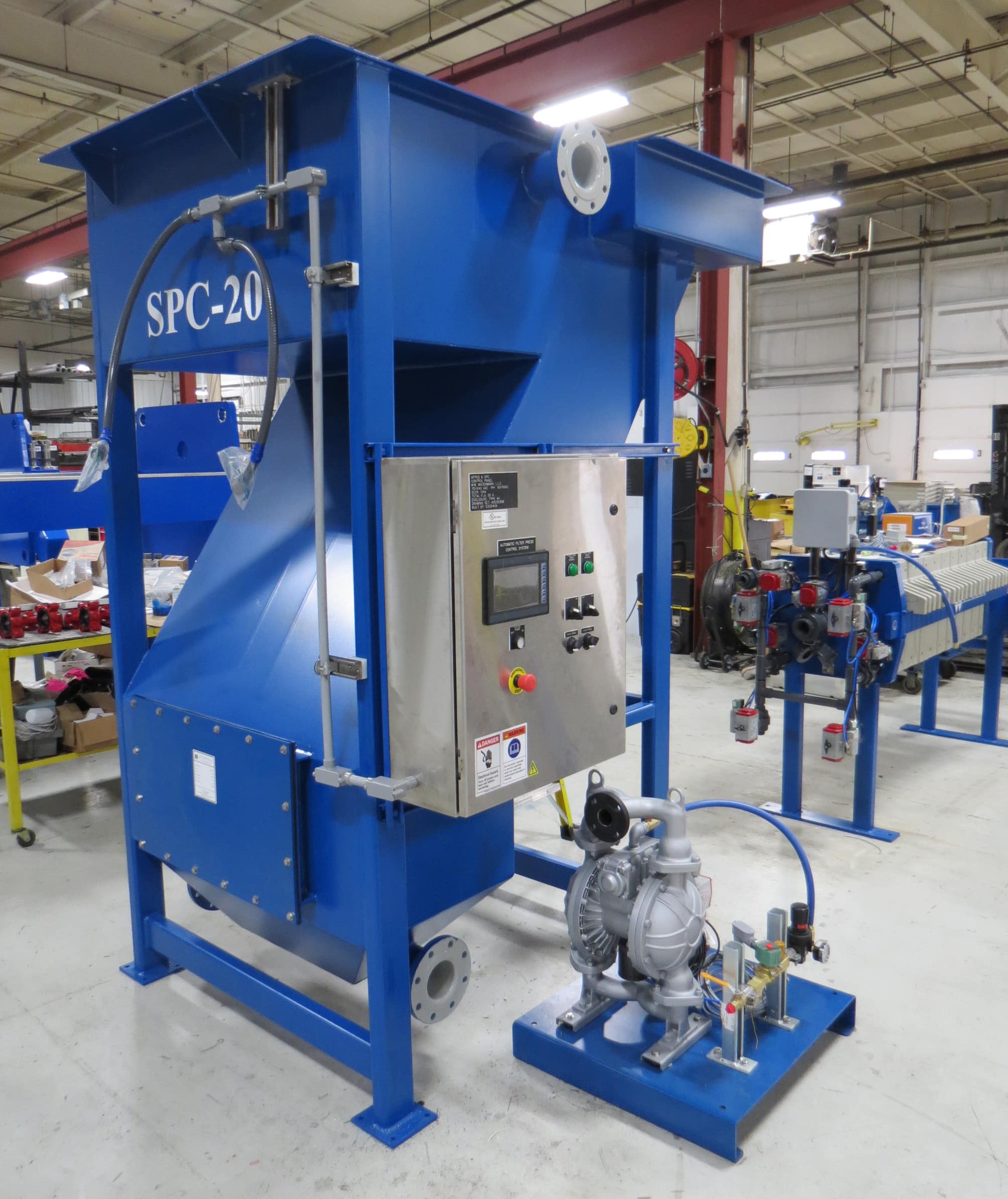
Photos of Selected Models

SPC-20

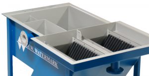
Flash Mixing Tank, Flocculation Tank, and Inclined Plates
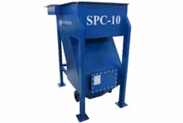
SPC-10
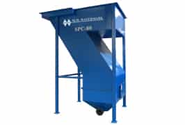
SPC-80
SPC-40 (Stainless Steel)
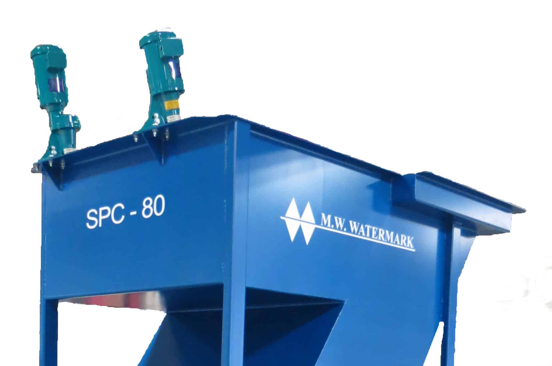
SPC-80 (Shown with Optional Mixers)
SPC-40 (Tnemec Chemical-Resistant Internal Coating)
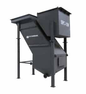
SPC-150 (Enduroliner™ External Coating)
Slant Plate Clarifier System Design
Fluid is fed into the top of the wastewater clarifier (A) and flows under a baffle to the integral flash mixing tank (B). At this point, a flocculating agent may be added with a PolyMark™ polymer blending system, and is blended with the fluid using an optional high-speed mixer. From the flash mixing tank, the fluid flows over a baffle into the integral flocculation tank (C), which may include an optional low-speed mixer. From here, the fluid flows through the feed channel, between the two plate stacks, and down to a sludge chamber, located at the bottom of the structure. Large particles begin to drop out of suspension as the velocity of the fluid decreases.
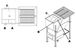
As the liquid enters the bottom of the plates and flows between settling plates, it maintains a low velocity, laminar flow profile which allows the suspended solids to settle on the lower plate, then flow downward to the sludge holding tank. While the solids are settling along the plate surfaces, the fluid is gradually heading upward through the plate stacks, over the weirs, and into the discharge trough.
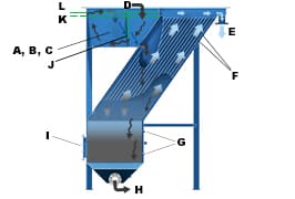
Finally, the clarified effluent is discharged through a flanged pipe connection. Through sample ports, operators are able to judge the sludge level, which is periodically pumped into a batch storage tank for further liquid-solid separation via an M.W. Watermark Filter Press and eventual disposal.
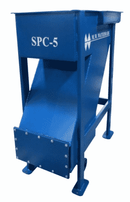
SPC-5
| Key | |
| A-C | Flash & Flocculation Tanks |
| D | Influent |
| E | Clean Effluent Liquid |
| F | Modular Laminar Plates |
| G | Thickening Sludge Ports |
| H | Sludge Removal |
| I | Access Hatch |
| H | Sludge Removal |
| J | Baffle |
| K | Overflow Weir |
| L | Waterline |
M.W. WATERMARK SLANT PLATE CLARIFIER SPECIFICATIONS
| Slant Plate Clarifier (SPC) Model | SPC-5 | SPC-10 | SPC-20 | SPC-40 | SPC-80 | SPC-150 | SPC-200 | SPC-300 | SPC-400 |
| Design Flow Maximum (GPM) | 5 | 10 | 20 | 40 | 80 | 150 | 200 | 300 | 400 |
| Flash Tank Mix Volume (gal) | 4.4 | 4.5 | 38 | 50 | 79 | 110 | 110 | 186 | 186 |
| Flocculation Tank Volume (gal) | 6.5 | 20.5 | 62 | 99 | 189 | 316 | 316 | 742 | 742 |
| Total Pre-Treatment Vol. (gal) | 10.9 | 25 | 100 | 149 | 268 | 426 | 426 | 928 | 928 |
| Effluent Piping Connection (Class 150 Flange) | 1″ | 3″ | 4″ | 4″ | 4″ | 6″ | 6″ | 8″ | 8″ |
| Solids Discharge Connection (Class 150 Flange) | 1″ | 3″ | 4″ | 4″ | 4″ | 4″ | 4″ | 6″ | 6″ |
| Sludge Capacity (gallons) | 17 | 42 | 88 | 150 | 275 | 469 | 611 | 834 | 960 |
| Plate Area (ft2) | 19 | 38 | 91 | 198 | 345 | 728 | 1,153 | 1,339 | 1,633 |
| Projected Plate Area (ft2) | 8.9 | 20 | 49 | 107 | 189 | 400 | 633 | 747 | 911 |
| Empty Shipping Weight (lb) | 765 | 1,400 | 2,065 | 3,600 | 4,800 | 7,400 | 11,000 | 11,800 | 16,500 |
| Full Operating Weight (lb) | 1,325 | 2,875 | 5,310 | 9,000 | 15,480 | 22,900 | 32,760 | 56,550 | 60,320 |
| Overall Length | 45″ | 56″ | 70″ | 87″ | 104″ | 135″ | 163″ | 179″ | 210″ |
| Overall Width | 23″ | 44″ | 60″ | 60″ | 73″ | 77″ | 77″ | 90″ | 100″ |
| Overall Height | 51″ | 64″ | 94″ | 104″ | 129″ | 147″ | 147″ | 147″ | 143″ |
| Design Solids Removal (200ppm influent) | 95%+ | 95%+ | 95%+ | 95%+ | 95%+ | 95%+ | 95%+ | 95%+ | 95%+ |
| Underflow Solids (% by weight) | 1-2% | 1-2% | 1-2% | 1-2% | 1-2% | 1-2% | 1-2% | 1-2% | 1-2% |
*Removal efficiencies are contingent upon proper chemical make-up and application.
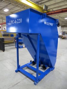
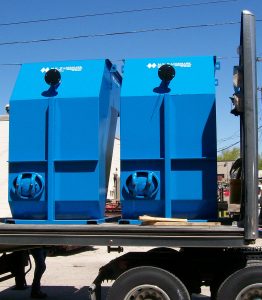
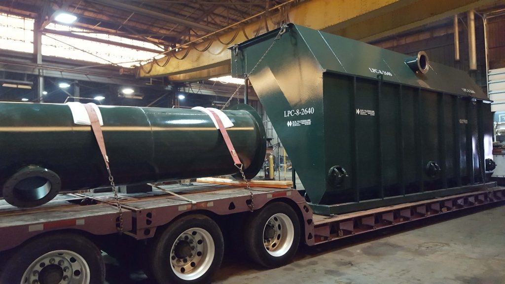
The M.W. Watermark Low Profile Clarifier (LPC)
M.W. Watermark low profile clarifiers are designed to provide efficient solids removal from a wide range of waste and process liquids. The settling plates are inclined at an angle of 55° with 1-inch spacing. The slope of the plates allows the solids to settle by gravity while the fluid moves upward through the plate stack.
Stacking the plates reduces the floor space required by the low profile clarifier compared to a horizontal clarifier. The inclined plate design allows the total gravity settling area to be as much as ten times the floor space occupied by the clarifier.
M.W. Watermark offers two series of low profile clarifiers, depending on ceiling height and design flow needs.
The LPC-4 Series offers a design flow maximum ranging from 30 to 300 GPM. – Download brochure
The LPC-8 Series ranges from 165 to 1,100 GPM. – Download brochure

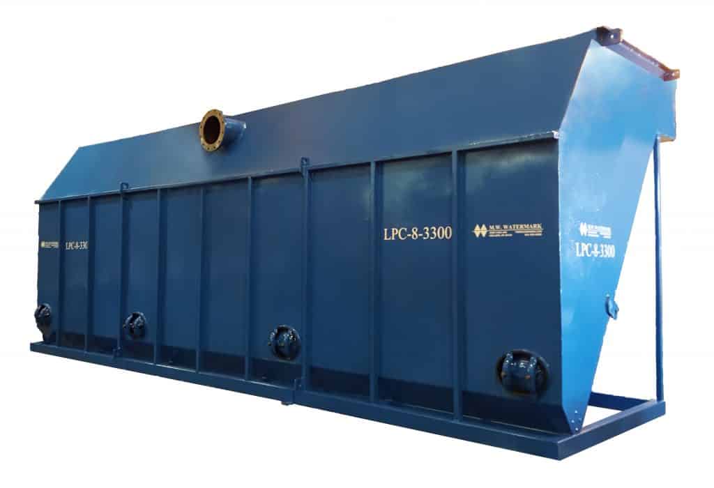
Low Profile Clarifier Product Features
- Standard models up to 300 GPM (LPC-4 Series) and up to 1,100 GPM (LPC-8 Series).
- Compact size minimizes floor space requirements.
- Heavy duty steel construction, welds are dye penetrant tested.
- Carbon steel units are sandblasted and two coats of epoxy applied to ensure full coverage and superior chemical resistance.
- 1/8″ polypropylene plates standard.
- Sludge outlet flanges.
- Access hatches standard.
Available Options
In addition to the standard features, our low profile clarifiers can also be equipped with:
- Chemical Addition Tanks (CAT) – Chemical pre-treatment for optimal solids removal. Tanks include mixers, chemical pumps and NEMA 4X UL-508A labeled panel.
- Influent feed, sludge discharge and effluent pumps.
- Custom designs available.
- PolyMark™ polymer delivery systems.
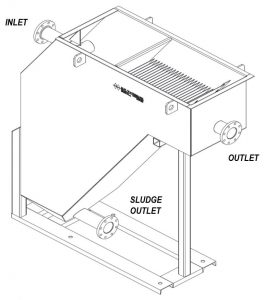
Low Profile Clarifier System Design
The raw enters the inlet chamber through a distribution baffle which disperses the water across the entire width of the tank. The inlet chamber reduces the velocities and turbulence in the water. Flow exits the bottom of the chamber into the sludge chamber.
From the sludge chamber flow then enters the bottom of the plate stacks and flows between the settling plates. Between each of the plates, the fluid has a low velocity, laminar flow profile which encourages the remaining solids to settle on the surface of the lower plate and flow downward to the sludge holding chamber.
As the solids are settling along the plate surfaces, the fluid is moving upward through the plate stacks, over and adjustable weir and into the effluent trough.
Clarified effluent is then discharged through an effluent flange. Sludge is periodically drawn off the bottom of the sludge holding tank at the bottom of the clarifier.
Sample ports can be provided to assist with determining the sludge level, which is periodically pumped to a batch storage tank for further solid-liquid separation via an M.W. Watermark filter press for eventual disposal.
M.W. WATERMARK LOW PROFILE CLARIFIER (LPC) 4 SERIES – SPECIFICATIONS
| Low Profile Clarifier (LPC) Model | LPC-4-110 | LPC-4-220 | LPC-4-330 | LPC-4-440 | LPC-4-550 | LPC-4-660 | LPC-4-770 | LPC-4-880 | LPC-4-990 | LPC-4-1100 |
| Design Flow Maximum (GPM) | 30 | 55 | 85 | 110 | 140 | 165 | 195 | 220 | 250 | 300 |
| Inlet/Outlet Connections (Class 150 Flange | 2 ½” | 4″ | 6″ | 6″ | 6″ | 6″ | 8″ | 8″ | 8″ | 8″ |
| Solids Outlet Connection (Class 150 Flange) | 4″ | 4″ | 4″ | 4″ | 4″ | 4″ | 4″ | 4″ | 4″ | 4″ |
| Projected Plate Surface Area (ft2) | 110 | 220 | 330 | 440 | 550 | 660 | 770 | 880 | 990 | 1,100 |
| Empty Shipping Weight (lbs.) | 1,800 | 2,400 | 3,200 | 4,000 | 4,800 | 5,600 | 6,400 | 7,200 | 8,000 | 8,800 |
| Flooded Weight (lbs.) | 6,000 | 11,000 | 17,000 | 22,000 | 27,000 | 32,000 | 37,000 | 42,000 | 47,000 | 52,000 |
| Overall Length | 7′-0″ | 7′-0″ | 7′-0″ | 7′-0″ | 7′-0″ | 7′-0″ | 7′-0″ | 7′-0″ | 7′-0″ | 7′-0″ |
| Overall Width | 2′-1″ | 4′-1″ | 6′-1″ | 8′-1″ | 10′-1″ | 12′-1″ | 14′-1″ | 16′-1″ | 18′-1″ | 20′-1″ |
| Overall Height | 7′-7″ | 7′-7″ | 7′-7″ | 7′-7″ | 7′-7″ | 7′-7″ | 7′-7″ | 7′-7″ | 7′-7″ | 7′-7″ |
| Design Solids Removal (Up to 1,000 mg/l) | 95%+ | 95%+ | 95%+ | 95%+ | 95%+ | 95%+ | 95%+ | 95%+ | 95%+ | 95%+ |
*Removal efficiencies are contingent upon proper chemical make-up and application.
M.W. WATERMARK LOW PROFILE CLARIFIER (LPC) 8 SERIES – SPECIFICATIONS
| Low Profile Clarifier (LPC) Model | LPC-8-660 | LPC-8-880 | LPC-8-1100 | LPC-8-1320 | LPC-8-1540 | LPC-8-1760 | LPC-8-1980 | LPC-8-2200 | LPC-8-2420 | LPC-8-2860 | LPC-8-3300 |
| Design Flow Maximum (GPM) | 165 | 220 | 300 | 330 | 385 | 440 | 500 | 550 | 630 | 950 | 1,100 |
| Inlet/Outlet Connections (Class 150 Flange | 6” | 8″ | 8″ | 10″ | 10″ | 10″ | 12″ | 12″ | 12″ | 14″ | 14″ |
| Solids Outlet Connection (Class 150 Flange) | 4″ | 4″ | 4″ | 4″ | 4″ | 4″ | 4″ | 4″ | 4″ | 4″ | 4″ |
| Projected Plate Surface Area (ft2) | 660 | 880 | 1,100 | 1,320 | 1,540 | 1,760 | 1,980 | 2,200 | 2,420 | 2,860 | 3,300 |
| Empty Shipping Weight (lbs.) | 5,700 | 7,000 | 8,100 | 9,100 | 10,600 | 12,600 | 14,800 | 15,000 | 16,000 | 19,500 | 22,000 |
| Flooded Weight (lbs.) | 29,000 | 38,000 | 47,000 | 56,000 | 65,000 | 74,000 | 83,000 | 92,000 | 100,000 | 120,000 | 140,000 |
| Overall Length | 9′-6″ | 9′-6″ | 9′-6″ | 9′-6″ | 9′-6″ | 9′-6″ | 9′-6″ | 9′-6″ | 9′-6″ | 9′-6″ | 9′-6″ |
| Overall Width | 6′-1″ | 8′-1″ | 10′-1″ | 12′-1″ | 14′-1″ | 16′-1″ | 18′-1″ | 20′-1″ | 22′-1″ | 26′-1″ | 30′-1″ |
| Overall Height | 11′-6″ | 11′-6″ | 11′-6″ | 11′-6″ | 11′-6″ | 11′-6″ | 11′-6″ | 11′-6″ | 11′-6″ | 11′-6″ | 11′-6″ |
| Design Solids Removal (Up to 1,000 mg/l) | 95%+ | 95%+ | 95%+ | 95%+ | 95%+ | 95%+ | 95%+ | 95%+ | 95%+ | 95%+ | 95%+ |
*Removal efficiencies are contingent upon proper chemical make-up and application.
Contact M.W. Watermark
To learn more, please contact the M.W. Watermark Sales and Service team.
